Building a 10-module split-flap display
I’d been wanting to build a split-flap display for a while. Back in 2020 I started gathering parts for Scott Bezek’s design - the laser-cut version with custom PCBs. I bought a bunch of 12V 28BYJ-48 stepper motors and hall-effect sensors and then… life happened, and the project sat in a box.
Fast forward to 2025, and I decided to actually finish this thing. But, the thing which kept me from finishing the project during the pandemic was still relevant: cutting out and labeling hundreds of individual flaps wasn’t a very appealing use of time. Thankfully, there’s more mechanical design out there these days. I modified a 3D-printed design from Makerworld, designed and built some custom electronics, and with a bit of debugging I have a fully working display! Here’s the finished product:
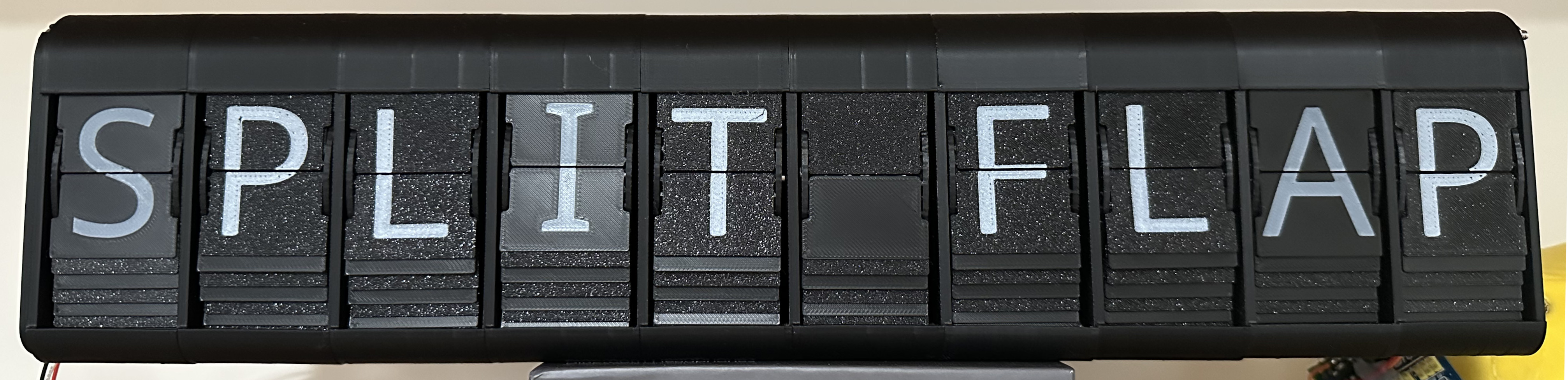
The completed 10-unit split-flap display
Project details⌗
Like most projects, getting this one out the door was a bit of a winding path, and with more than a little sunk-cost fallacy. I came back to this project because I had a bit of a break between leaving Stripe and starting the new job.
Mechanical⌗
I’ve always liked working with electro-mechanical systems – it’s a lot of why I studied robotics, though my career since then has trended more in the software side of things. The main mechanical challenge of a split-flap display is that there are actually a lot of individual mechanical pieces, and even just assembly is nontrivially time-consuming. Each character in the display has 48 flaps, a spindle, an outer enclosure, and various retaining clips - even before getting into the electronics!
Thankfully, since I was using an existing Makerworld design, I didn’t have to change much to get things to work. There are only two modifications I’ve made to the base design:
- I didn’t want to use the same driver setup as the original, so I edited the enclosure to make more space to fit the wire harnesses and miscellaneous pieces.
- I replaced the 3D-printed shaft that the spindle rests on with a metal shelf pin. This was necessary because my 3D printer can’t print a good enough cylinder to prevent binding on the spindle, which made the system really unreliable.
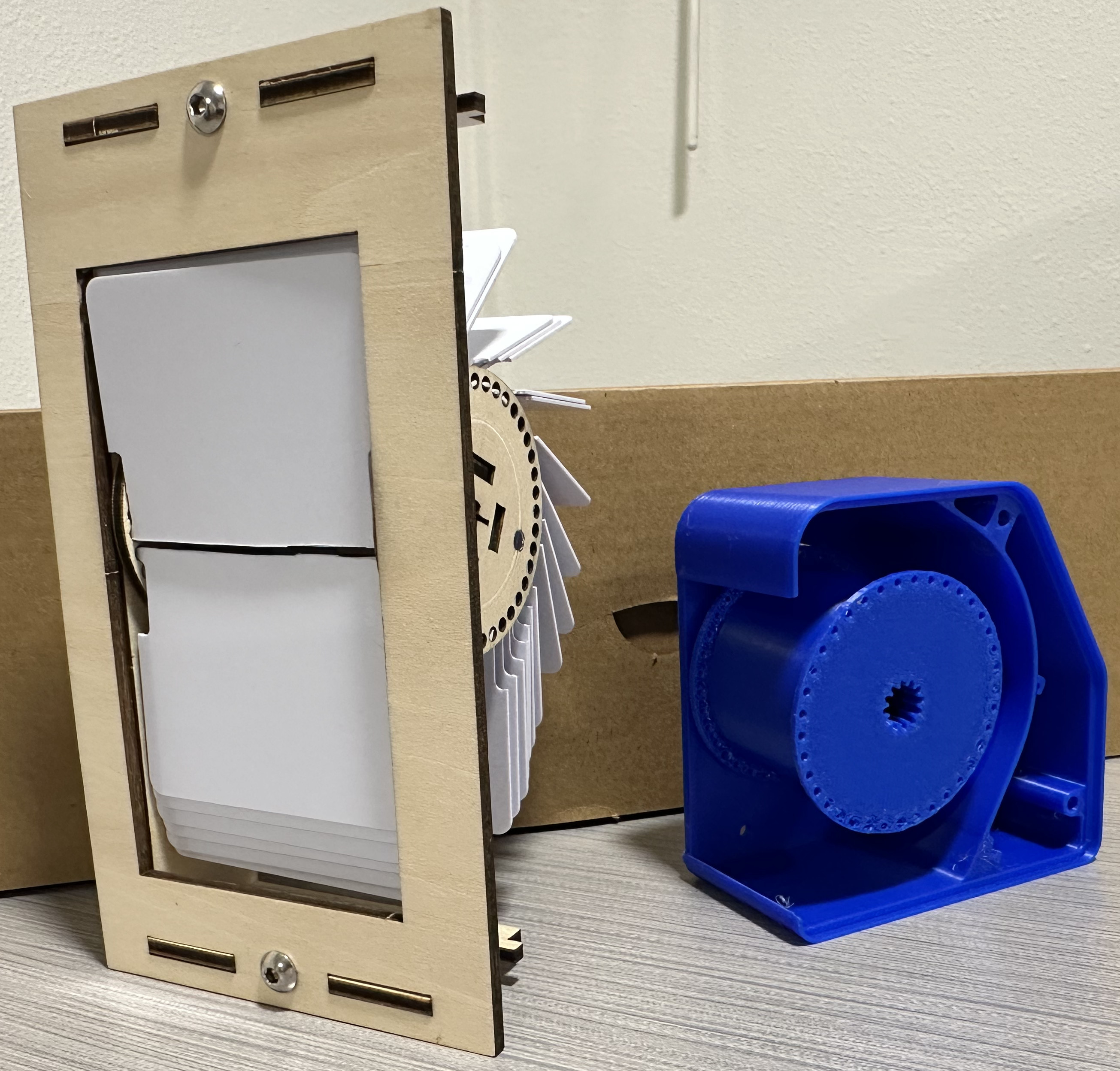
Laser-cut enclosure (left); A prototype of the 3D-printed version (right)
Unfortunately I didn’t take many pictures of the in-progress build. I didn’t do too much interesting here other than suffer through printing and assembly, so the original sources are probably better for pictures.
Electrical⌗
The electrical design was a bit more interesting. The Makerworld design relies on COTS I2C I/O expanders connecting to ULN2003 transistor arrays to power the stepper coils, orchestrated by an ESP32 microcontroller. I thought that it was especially neat that the individual modules were daisy-chained together rather than my initial prototypes’ need for longer and longer wires running back to the control board.
Unfortunately, there were a bunch of reasons that this wouldn’t trivially work for me:
- The PCF8574 I2C I/O expanders have a small, finite number of addresses. Daisy-chaining more than 8 modules would require more components and complexity
- I had 12V 28BYJ-48 stepper motors and A3144 hall-effect sensors already, but I didn’t have any of the ULN2003 arrays. Instead, I had stepstick-compatible A4988-based stepper motor drivers.
Also, each of the original designs required some tricky soldering of breakout boards together so they would carefully fit in the designated space. I’ve long ago lost the patience for repeated soldering in weird configurations.
Thankfully, it turns out you can design custom PCBs and get them assembled very cheaply. In fact, since the component sourcing can be done in China where the PCBA happens, it can even be cheaper than ordering the components in small quantities in the US and assembling at home. In particular, I wanted to use wire harnesses terminated with “JST” 6-pin 2.5mm connectors; these things are annoyingly expensive if you aren’t buying 1000 of them.
It’d been a while since I’d done a PCB design, so I played with a few different ideas. The key design decisions were the communications protocol, the logic-level control setup, the motor driver setup, and how much of the logic to put on the ESP32 vs. on the various daughterboards.
Each splitflap unit has a 28BYJ-48 unipolar stepper motor and an A3144 hall-effect sensor on board. Driving the unipolar stepper requires 4 transistors to be triggered in a specific sequence. Reading from the hall-effect sensor (for homing) requires a smaller amount of traffic in the other direction.
Scott Bezek chose a shift-register based protocol using 74HC595 and 74HC165 shift registers, with the ratios set up so that there are far fewer input registers than output registers. This makes sense given the massive number of units he tends to run at once, but the minimum number of units controlled per board starts to add up pretty quick. I really liked the modularity of the original Makerworld design, and didn’t want the total size to be sets of 8. The nice thing about the shift-register design, though, is that it makes daisy-chaining pretty straightforward – the popular ws2812b RGB LEDs also use a shift register for this reason.
The Makerworld design dedicates a PCF8574 per unit, as I mentioned earlier. I wasn’t necessarily opposed to this, but between buying a PCF8574, a ULN2003 motor driver, and a bunch of connectors the electronic part cost was starting to add up - and I’d still have to assemble everything by hand.
I realized that two silly things are true about hobby electronics in 2025:
-
Popular breakout boards can be bought for much less than their low-quantity parts cost. For example, an A4988 stepper motor driver runs for about $3.50 as a bare part, but a fully populated breakout board (including passives and a heatsink) costs between $1.50-$2.00 in quantities of 5-10. The ULN2003 transistor array is slightly cheaper (around $0.60/ea), but you need a lot more pins to use it.
-
PCBA costs are so cheap now that it’s really only the cost of shipping and tariffs; the actual boards can easily go down to $6-8/each in small quantities.
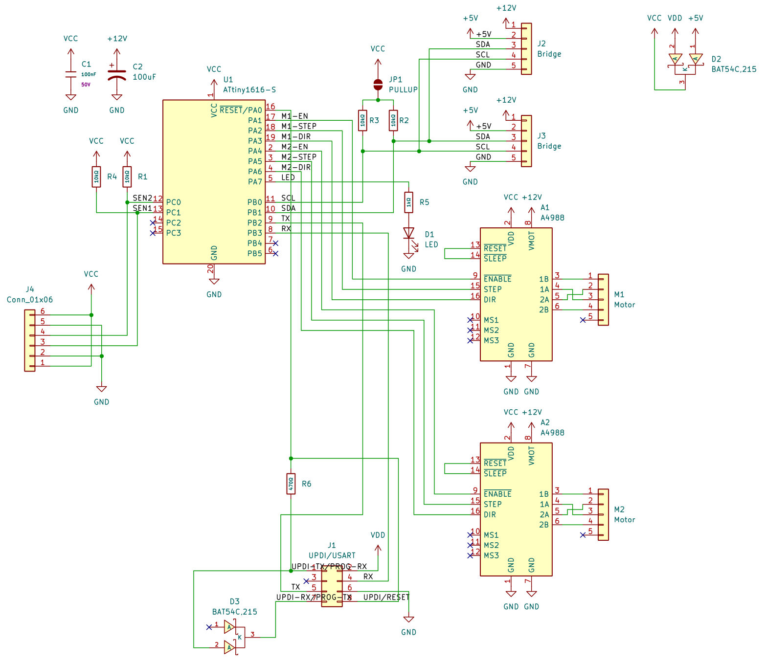
Schematic for the control board - I have gerbers if you are curious
So, I decided to design a small daughterboard and use it as an excuse to play with the newer ATtiny 1-series parts. Conveniently, these are actually very cheap, have about the right number of pins, and have onboard I2C and USART. One kind of neat thing is that they have a single-wire programming interface (“UPDI”) which you can talk to using a slightly hacked USB serial converter. Each control board fits two A4988 breakouts and has all of the passives necessary to manage sensors and communications, plus it comes with the 2.50mm connectors already soldered.
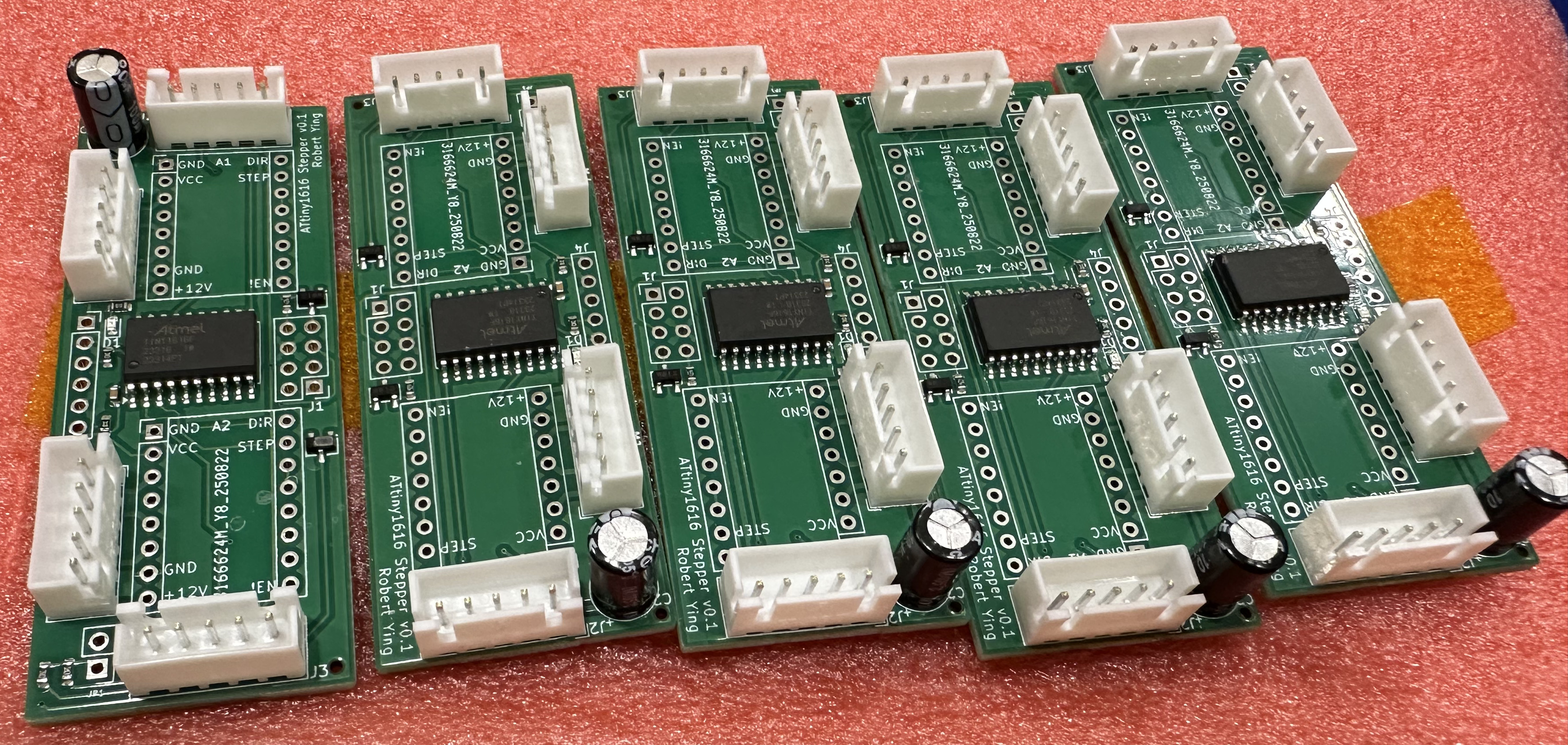
Custom PCBA motor control board
Part of the reason to have a proper microcontroller on board was to take the communication latency out of the motor control loop. While many of the other designs are happy to have the motor stepping controlled directly by the ESP32, I saw that in my earlier prototype each successive motor would be just a little bit delayed, creating an undesirable rippling effect. Having the sensor, motor driver, and controller on the same side of the communication bus meant that the relevance of the bus speed to mechanical action was minimal.
The I2C interface is a simple register map:
Motor 1: 0x00-0x0B  |  Motor 2: 0x10-0x1B
---------------------------------------------
0x00: Target position (16-bit, R/W)
0x02: Current position (16-bit, R/O)
0x04: Steps per rotation (16-bit, R/W)
0x08: Control byte (direction, etc.)
0x0B: Speed in RPM (8-bit, R/W)

Global:
0x20: Status (bit flags for "at target" and sensor states)
The motors auto-enable when moving and auto-disable when stopped. Configuration persists to EEPROM. The host doesn’t need to manage timing at all - just set targets and wait for the status register to show completion.
Of course, designs are all well and good, but with reality often comes new problems. And, in this case, different problems than I’d anticipated. I thought I’d end up with a pretty annoying state-machine / programming effort for the ATtiny1616s, but actually once I gave a sufficiently good prompt to Claude Code (Sonnet 4), I got a pretty decent firmware in only a few minutes.
Hurdle 1: Getting the theoretical UPDI programmer to work was pretty annoying, but mostly because I didn’t know what I was doing. I’d designed an appropriate resistor and diode into each board to allow me to use a regular USB serial adapter for programming. But, the USB serial adapters I used didn’t work at first, until I realized that the TX and RX LEDs parallel to the UART were interfering with the UPDI protocol. Desoldering those subcircuits got programming to work very reliably. I think I’ll probably do more with the microcontrollers, they’re neat and very cheap.
Hurdle 2: After assembling a few of the units, I was feeling pretty confident. Unfortunately, the whole thing stopped working consistently once I got to 4 daisy-chained boards (8 units), and I wanted to get to 5. It turns out that I had forgotten that I2C is designed for communication within a single board, and since I was using 10cm wire harnesses to connect each board together, the bus capacitance was actually quite high. Claude came to my rescue again, and I swapped my 4.7k pull-up resistors to 1k. The issue hasn’t recurred since.
The result⌗
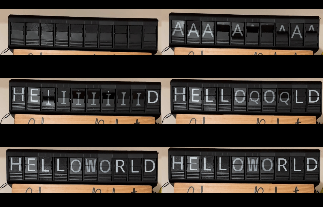
The display in action
This thing has been running pretty well for the last few months, and it’s a great source of entertainment for the kiddo. Still not the world’s most information-dense display – there are good reasons why we don’t use these things anymore – but I had a good time working on it and was happy to finally finish this pandemic project.